Robots Are Repeatable. So Why Are Printed Parts Still Wrong?
Robot repeatability is only one link in a long chain from CAD to a physical part. Toolpaths, controllers, calibration, external axes and material behavior can turn a correct virtual plan into an incorrect build.
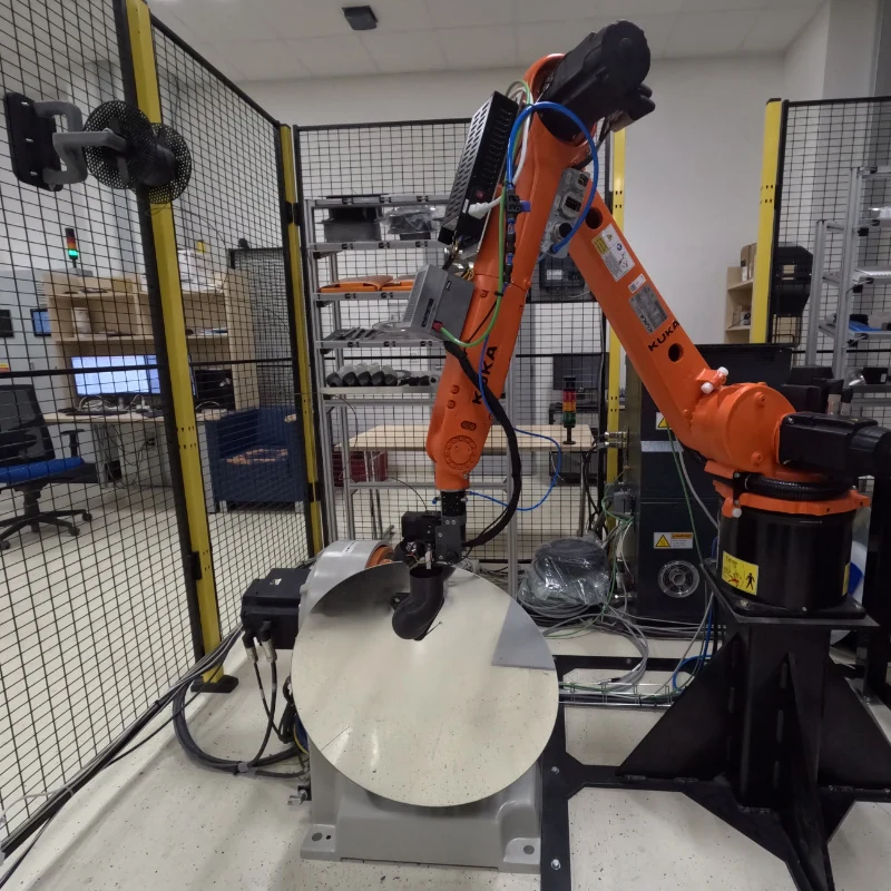
Industrial robots are often described by their repeatability. A datasheet may state that a robot can return to a pose within a few hundredths of a millimetre.
That number is important, but it does not mean that a multi-axis printed part will be accurate to the same value.
This difference between a robot's nominal capability and the final manufacturing result has been central to the work of Tomáš Jochman, whose robotics research helped shape QH Build's controller-aware simulation layer. After more than seven years working with robotic simulation software, industrial controllers, CAM systems and digital twins, he learned that the difficult question is not whether a robot can repeat a point. It is whether the entire digital-to-physical chain behaves as expected.
The error chain starts before the robot moves
A robotic additive process begins with geometry, but the geometry passes through several transformations before it becomes a physical part:
- A CAD model is decomposed and sliced.
- CAM software creates an ideal toolpath.
- A postprocessor converts the path into robot code.
- A virtual robot controller interprets motions, blending and interpolation.
- The real controller drives the robot and any external axes.
- The deposition system starts, stops and changes material flow.
- The real material melts, flows, cools and solidifies.
Each step can introduce an error. More importantly, the errors can accumulate.
A slicer may approximate a curved edge. A postprocessor may handle a transition differently from the CAM preview. A controller may blend a corner and reduce the actual tool speed. A manually calibrated tool or positioner may be offset. Robot stiffness and temperature can influence the executed trajectory. The deposited material may then spread or shrink in a way that a purely geometric simulation cannot represent.
This is why a digital twin must be more than a 3D model of a robot.
Building a digital twin around the real process
In the INDIN 2024 study led by Tomáš, the team created a digital-twin workflow for robotic multi-axis additive manufacturing using a KUKA six-axis robot, a two-axis rotary-tilt positioner, an extrusion head, a virtual robot controller and precision metrology.
The framework connected several layers:
- CAM simulation for slicing, path planning and collision checking;
- virtual robot controller simulation for the actual robot program and controller behaviour;
- empirical calibration of the robot workspace, positioner, tool and printing pad;
- process-parameter calibration for material flow;
- controller data acquisition for monitoring and comparison;
- 3D scanning of the printed part for final deviation analysis.
A laser tracker was used to align the virtual coordinate systems with the physical cell. The calibration procedure used measured robot positions and singular value decomposition to calculate transformations between coordinate systems. The positioner plane, centre and axes were measured as well. Even the printing pad was mapped and compensated using bilinear interpolation because a small height deviation can determine whether the first layer bonds correctly.
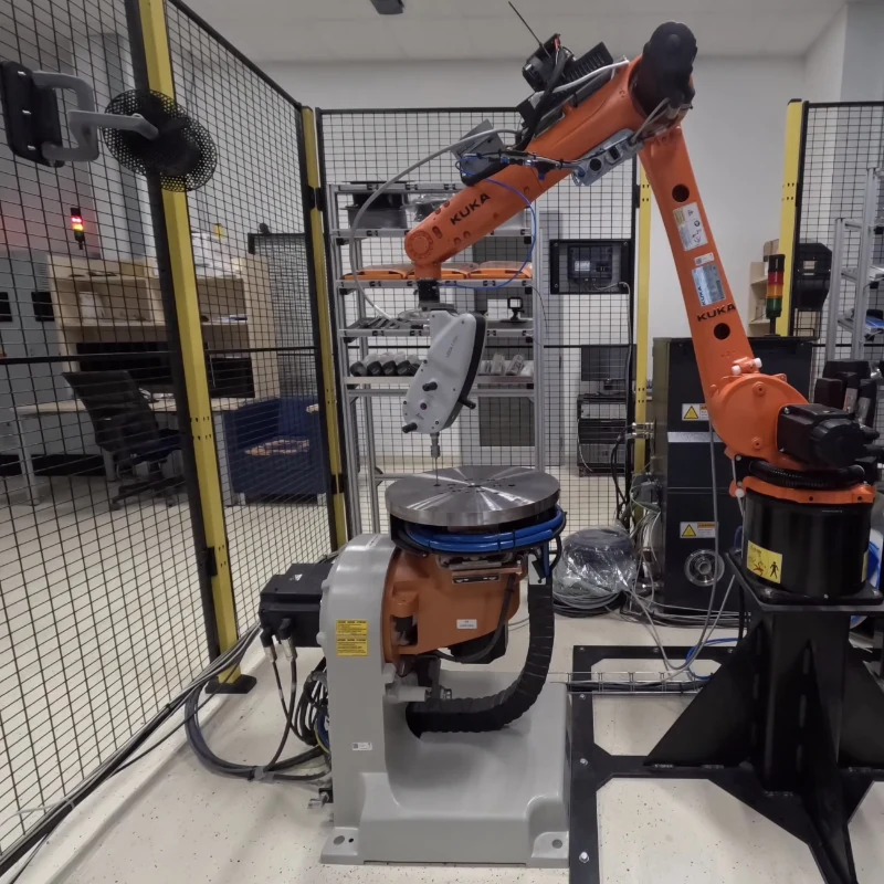 Calibrated robot and two-axis positioner used in the multi-axis additive-manufacturing workflow
The controller changes the geometry
One of the most important findings was that different motion strategies produced different physical errors even when they were intended to create the same nominal shape.
For a cylindrical feature, the team compared planar and helical slicing and tested whether rotational motion should be performed mainly by the robot or by the positioner. Laser-tracker measurements showed that the smallest real-world error occurred when the robot moved along the vertical axis while the positioner performed the rotation using planar slicing.
The alternative robot-dominant motion created oscillation around the target trajectory. That oscillation produced a visibly wavy deposited surface. In a multi-layer build, such a wave is not merely cosmetic: it can change the cylinder diameter, cause the nozzle to approach the previous layer incorrectly, or lead to material being deposited outside the intended boundary.
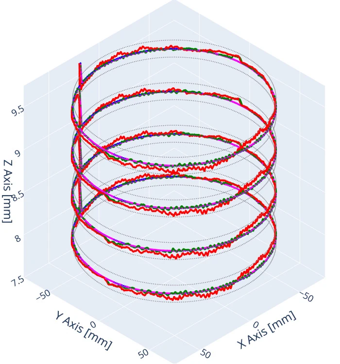 Measured planar robot trajectory compared with the programmed and simulated motion
The crucial lesson was that conventional CAM or virtual-controller checks could not fully reveal which strategy would produce the best physical result. Metrology and process-aware simulation were needed to close the gap.
Repeatability is not manufacturing accuracy
The study printed a propeller-like part and a curved tube, then compared the CAD model, the simulated in-process workpiece and the scanned physical parts.
For the virtual CAD-to-IPW comparison, more than 75% of the measured points were within approximately ±0.09 mm. For the physical builds, 75% of the points were within approximately ±0.6 mm for the curved tube and ±0.8 mm for the propeller.
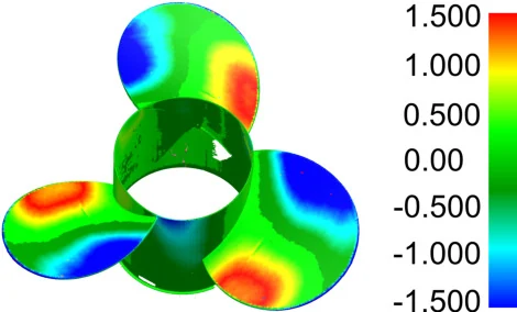 Deviation analysis comparing the produced propeller-like part with its target geometry
That difference is the manufacturing gap in numerical form. The virtual path can be internally consistent while the physical process still accumulates controller, calibration and material effects.
The study did not claim that every error could be removed. Instead, it showed that errors can be identified, assigned to stages of the workflow and reduced systematically.
Why this matters to industry
A controller-aware digital twin can help an engineering team answer practical questions before running a build:
- Which axis should perform a rotation?
- Will motion blending create local over-deposition?
- Is the tool, base or positioner calibration good enough?
- Does the robot program reproduce the CAM intention?
- Where should a part be scanned and what deviation should be expected?
- Which errors come from motion and which require a physical process model?
These questions apply beyond additive manufacturing. The same principles are relevant to robotic welding, cladding, machining, inspection and other processes in which path accuracy and process behaviour are tightly coupled.
At QH Build, this robotics layer became the foundation of the Kinematic and Dynamic Deposition Model. Its purpose is to represent the motion the controller actually executes, not only the path an engineer intended to program.
Because in production, the robot does not follow a screenshot. It follows a controller.
Technical basis
- Tomáš Jochman et al., Bridging the Gap: Digital Twin Integration and Evaluation in Robotic Multi-Axis Additive Manufacturing, IEEE INDIN 2024. DOI: 10.1109/INDIN58382.2024.10774248.