From KUKA + Meltio to a Scalable Multi-Axis Platform
Our first production-oriented MVP is grounded in a real KUKA and Meltio wire-laser cell. The architecture is being built so the same simulation framework can expand to ABB robots, new laser heads and different multi-axis configurations.

A scalable industrial platform should begin with a specific machine that has real constraints, not with a generic animation.
The first QH Build MVP is based on a robotic wire-laser additive manufacturing cell combining a KUKA industrial robot, a coordinated two-axis positioner and a Meltio deposition head. This setup gave us exactly the integration challenges the platform needed to solve: controller communication, external axes, process timing, calibration, laser-wire alignment, sensor data and multi-axis accuracy.
The reference cell
The validation platform described in our recent work used:
- a six-axis KUKA IONTEC industrial robot;
- a KRC5 robot controller;
- a KP2-HV500 two-axis positioner;
- a Meltio Engine V2 wire-laser head with up to 1,200 W laser power;
- 316L stainless-steel wire;
- laser alignment, load-cell information, shielding-gas control and thermal sensing;
- Siemens NX for multi-axis slicing and KRL robot-code generation.
The physical cell was mirrored in NVIDIA Omniverse so the same robot, external axes, process equipment and manufacturing sequence could be executed virtually.
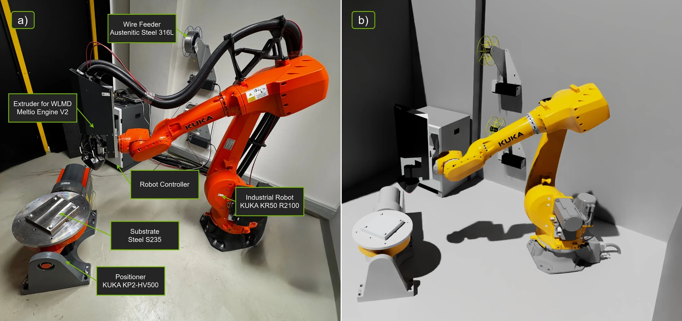 Physical and virtual robotic WLAM cell
Communication is part of the process model
Connecting a robot to a process head is not only a networking task. The timing and semantics of each signal affect the deposited material.
The reference implementation used two communication layers:
- digital I/O handshakes for deterministic macros such as initialization, start deposition, end deposition and material change;
- TCP/IP communication for process setpoints and data, including feed-speed instructions, laser-power instructions, gas-flow instructions and load-cell readings.
The same start-stop logic was mirrored in a Virtual Meltio Controller inside the Omniverse application. This allowed the virtual process to reproduce actuation delays and confirmation signals instead of switching material flow instantaneously.
For controller-aware robot state, the framework can use the virtual controller or stream data from the real KUKA system. Robot frames can also be recorded and replayed deterministically, which is valuable when comparing several simulation models against exactly the same motion.
Why multi-axis accuracy is difficult
The robot datasheet is not enough to predict deposition accuracy.
The final result depends on:
- the calibrated robot base and tool coordinate systems;
- the position and orientation of the external positioner;
- the wire and laser alignment;
- standoff distance between the head and deposited surface;
- coordinated robot-positioner interpolation;
- acceleration, motion blending and local tool speed;
- start-stop timing and wire-feed dynamics;
- thermal deformation of the part and substrate.
A multi-axis strategy can improve access and keep the process in a favourable orientation, but every additional controlled axis creates more possible motion distributions. The same nominal path can be executed by the robot, the positioner or a coordinated combination. Those choices influence accuracy and deposition quality.
That is why our simulation connects the real controller behaviour to material deposition rather than treating external axes as a visual accessory.
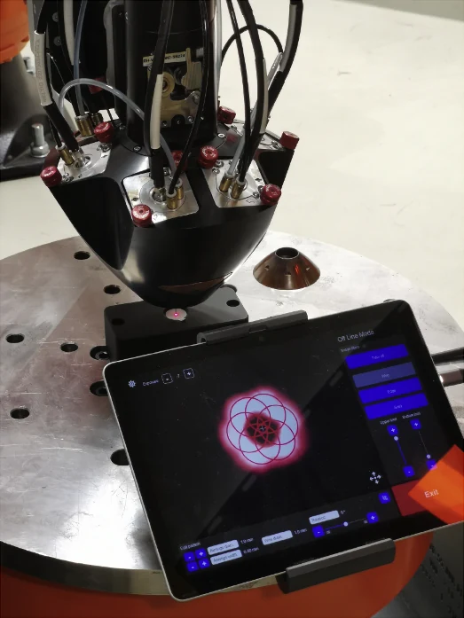 Camera view used to evaluate wire and laser alignment at the deposition head
What the first MVP needs to do
The MVP is focused on an end-to-end industrial workflow:
- Load the real robot, positioner, head and workpiece into an OpenUSD scene.
- Connect to the virtual or physical robot controller.
- Normalize robot and external-axis data into a common internal format.
- Execute the program and update the complete cell in the digital scene.
- Mirror process-head commands and timing.
- Run KDDM to predict controller-induced geometric deposition defects.
- Select critical regions and process conditions for MPDM simulation.
- Compare the prediction with sensors, robot logs and 3D scans.
This is intentionally narrower than a finished universal product. A reliable connector and validated data pipeline are more valuable than a long list of unsupported machine logos.
Scaling beyond the first cell
The architecture is being designed so machine-specific components are adapters rather than assumptions embedded throughout the software.
For a new robot family, the connector should provide normalized joint positions, Cartesian state, timing, I/O and program events. The simulation layer should not care whether the source is KUKA, ABB or another industrial controller.
For a new deposition head, a process adapter should describe commands, delays, limits, beam properties, wire feed, gas flow and available sensors.
Each new machine will still require calibration. Robot kinematics, beam profile, tool geometry, process delays and material properties are physical realities that cannot be solved by a generic configuration file alone. The benefit of the platform is that the calibration workflow and simulation interfaces can remain consistent.
Industrial value of a machine-independent digital thread
A scalable platform can help manufacturers:
- evaluate a new cell before installation;
- compare robot and positioner strategies;
- transfer a validated process to another machine with traceable recalibration;
- replay production data for root-cause analysis;
- test parameter changes without risking an expensive part;
- standardize simulation and monitoring across a fleet of cells.
The KUKA + Meltio setup is our first reference implementation because it is complex enough to expose the real problem. The product opportunity is to turn what we learned there into a repeatable framework for many industrial machines.
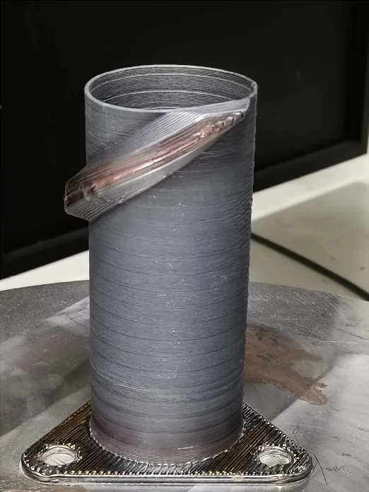 Production-scale WLAM part manufactured with the reference workflow
Technical basis
- Tomáš Jochman, Mehdi Abdi et al., Digital twin-ready acceleration of production-scale wire laser additive manufacturing using NVIDIA Omniverse, Results in Engineering 30 (2026) 111005. DOI: 10.1016/j.rineng.2026.111005.