Let's Talk Microstructure: What We Found Inside Our DED-W Samples
A dense, accurate part is only the beginning. Microscopy and mechanical testing reveal how thermal history creates directional structures and properties inside wire-based directed-energy-deposition builds.
A metal additive part can have the right dimensions, a smooth surface and almost no visible porosity - and still behave differently from the material assumed by the designer.
The reason is microstructure.
Every layer experiences rapid heating, melting, solidification and reheating from subsequent passes. That thermal history controls the grains, phases and local structures that form inside the material. Those structures then influence strength, ductility, fatigue response, corrosion behaviour and direction-dependent performance.
This is why QH Build's simulation roadmap does not stop at geometry or melt-pool prediction. We want to connect the complete chain:
process parameters → thermal history → microstructure → properties → part performance.
Looking inside 316L and ER70S builds
During our development work, wire-based directed energy deposition samples made from 316L stainless steel and ER70S low-carbon steel were analysed by the Institute of Physics of the Czech Academy of Sciences.
The reported manufacturing condition used a layer height of 0.8 mm and a laser power of 817 W. The characterization included:
- optical-microscopy porosity analysis using ImageJ;
- optical-microscopy examination of the microstructure;
- compression testing parallel and perpendicular to the printing direction.
The results provide a useful snapshot of what is hidden inside a seemingly simple deposited wall.
High density does not mean isotropic material
The porosity measurements showed high relative density for both materials:
- 316L: 99.93 ± 0.007%;
- ER70S: 99.88 ± 0.04%.
These are encouraging values. They indicate that, under the investigated condition, large void content was not the dominant issue.
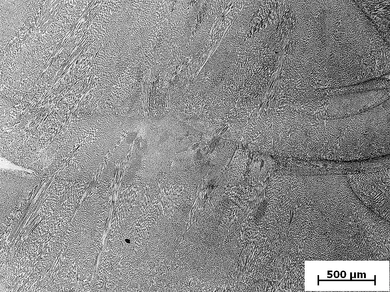
But density is only one quality indicator. The micrographs show directional structures connected to the build direction and repeated thermal cycles.
Representative 316L microstructure at a 500 micrometre scale
At higher magnification, the internal structure becomes more obvious. Regions with different orientations and morphologies appear across and within deposited tracks.
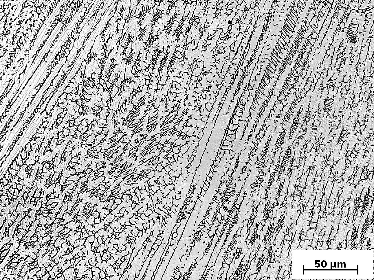 Higher-magnification 316L microstructure
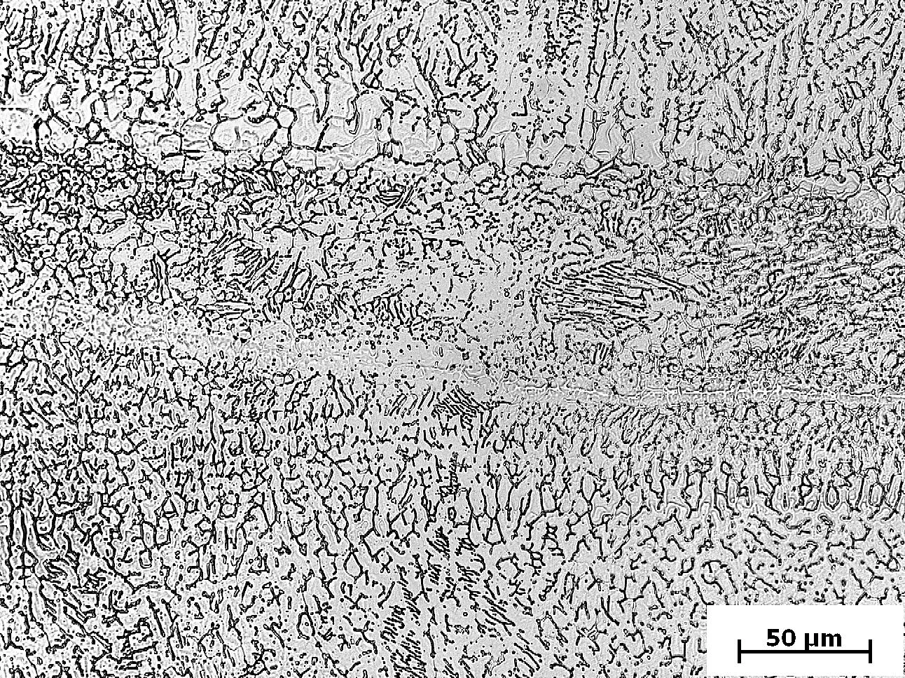 A second high-magnification view of the 316L deposited microstructure
The ER70S samples show a different microstructural appearance, as expected for a different alloy and transformation path.
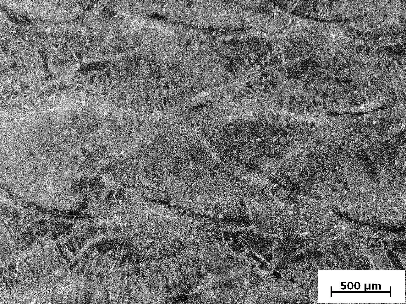 Representative ER70S microstructure at a 500 micrometre scale
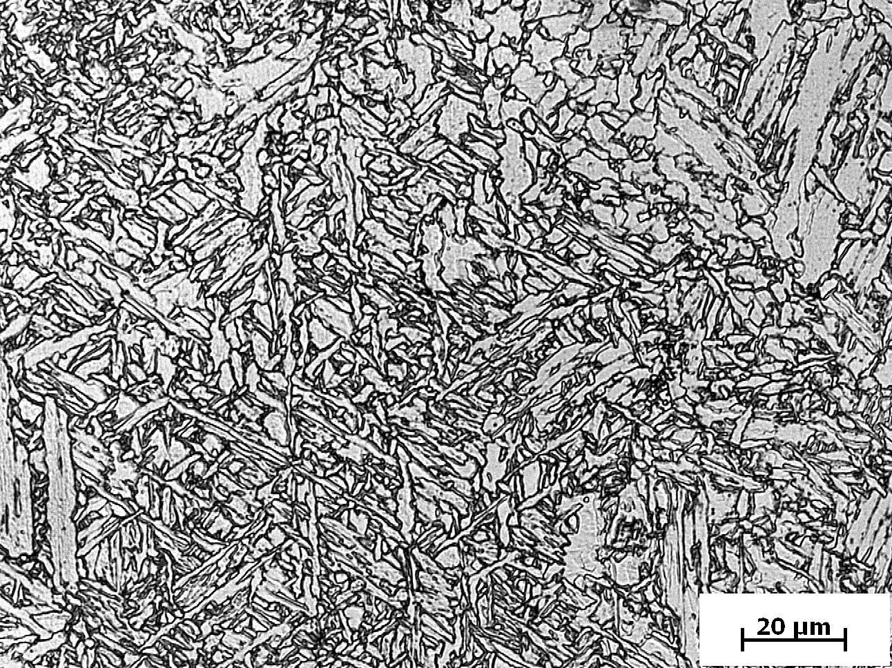 Higher-magnification ER70S microstructure
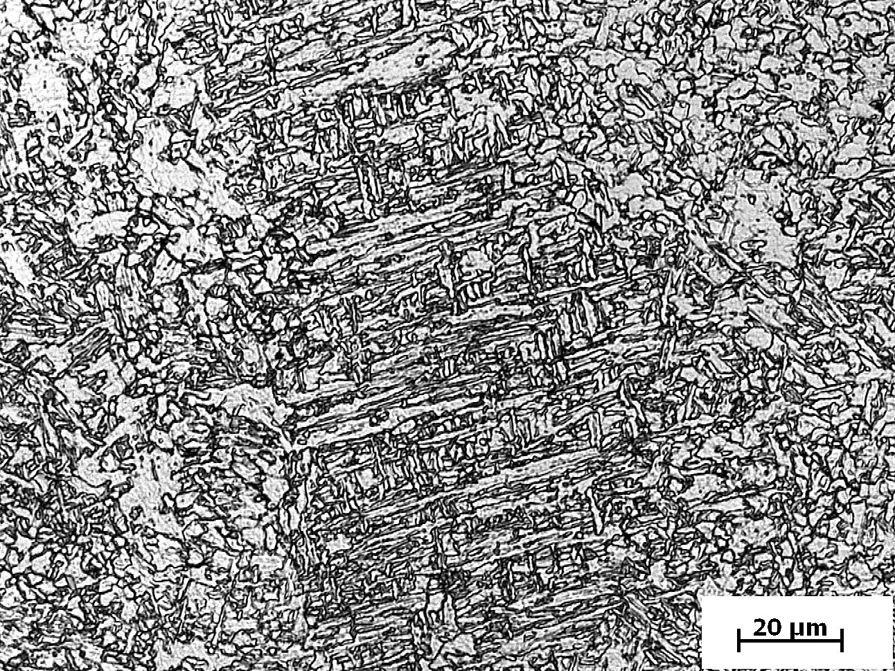 A second high-magnification view of the ER70S deposited microstructure
We intentionally avoid assigning detailed phase labels from these optical images alone. That would require supporting chemical, crystallographic or higher-resolution analysis. The reliable conclusion from the supplied results is that the deposited materials contain clear spatial and directional microstructural features that must be considered alongside porosity.
Why the printing direction matters
Compression specimens were tested in directions parallel and perpendicular to the printing direction. The resulting stress-strain curves were not identical.
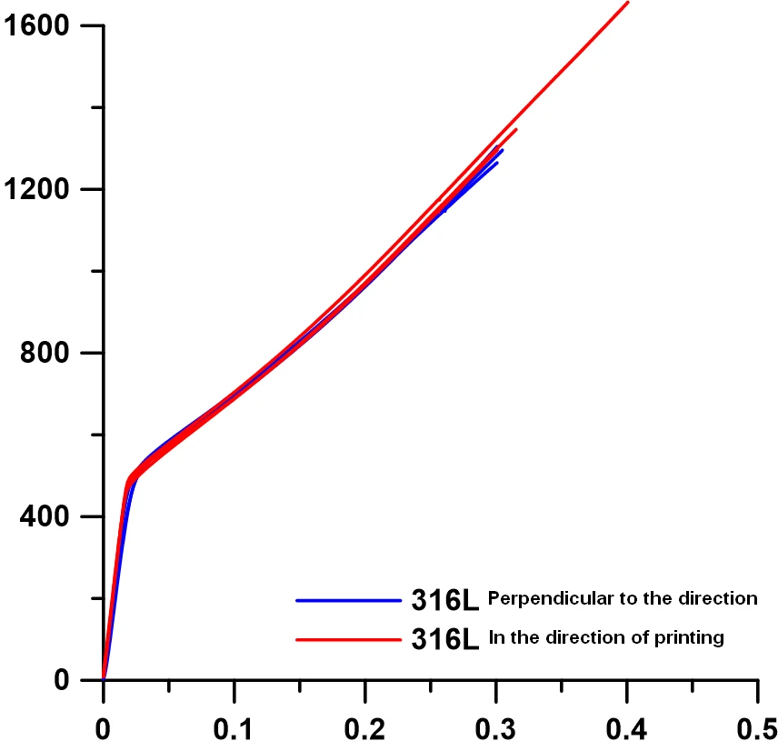 Engineering stress-strain response of the DED-W 316L compression specimens
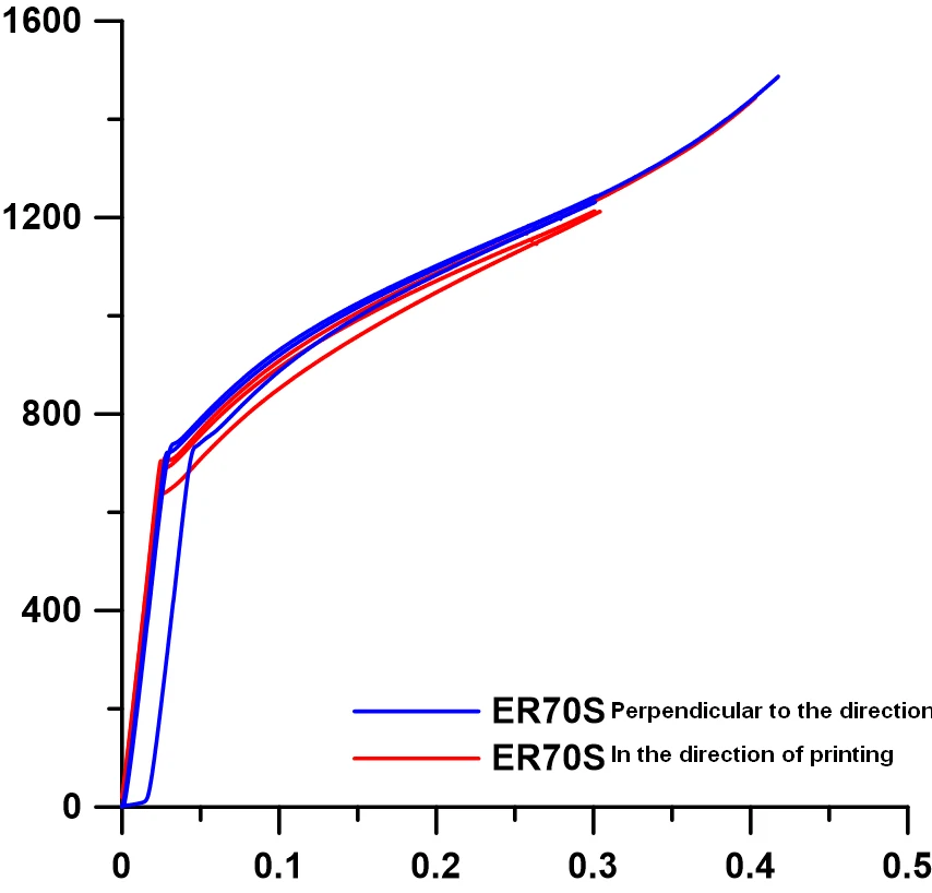 Engineering stress-strain response of the DED-W ER70S compression specimens
That does not automatically mean that one direction is universally “better.” It means that the build created a directional material response, and the response depends on the alloy, thermal history, sample orientation and test method.
For an industrial part, this matters because a load rarely follows the most convenient printing direction. A component may experience compression, tension, fatigue and thermal cycling across several orientations. A process qualified only by density or a single coupon direction may miss a critical weakness.
The simulation challenge
Predicting microstructure is much more difficult than displaying temperature.
A useful model needs to represent or infer quantities such as:
- local cooling rate and thermal gradient;
- solidification direction and interface velocity;
- repeated reheating from neighbouring tracks and later layers;
- phase-transformation kinetics where relevant;
- grain nucleation and growth;
- the effect of alloy composition and temperature-dependent properties.
It also needs the real robot path and process timing. A local deceleration changes energy per unit length. A different layer strategy changes heat accumulation. A pause or repositioning move changes cooling time. This is another reason robotics and materials simulation cannot remain disconnected.
From microscopy to a predictive digital twin
The microscopy and compression tests serve two roles.
First, they validate whether the physical process produces acceptable material under a selected parameter set.
Second, they create data for calibrating and evaluating future microstructure-evolution models. A simulation can predict thermal history, but it becomes industrially credible only when its predicted structures and properties are compared with measured samples.
For manufacturers, this capability could support:
- qualification of new materials and process windows;
- orientation-aware part design;
- prediction of property variation across large components;
- reduction of destructive testing during parameter development;
- transfer of a process between machines while preserving material quality;
- traceable evidence for demanding aerospace, energy or tooling applications.
A part is not finished when its shape is correct. It is finished when the material inside the shape can perform the required function.
That is why we are going deeper - from the robot path, through the melt pool, and into the microstructure.
Technical basis and publication note
- Source: 316L and ER70S produced by DED-W, March 2025, Angelina Strakošová, Institute of Physics of the Czech Academy of Sciences, Department of Functional Materials.
- The microscopy and test visuals are reproduced from the media set verified by QH Build for this article.